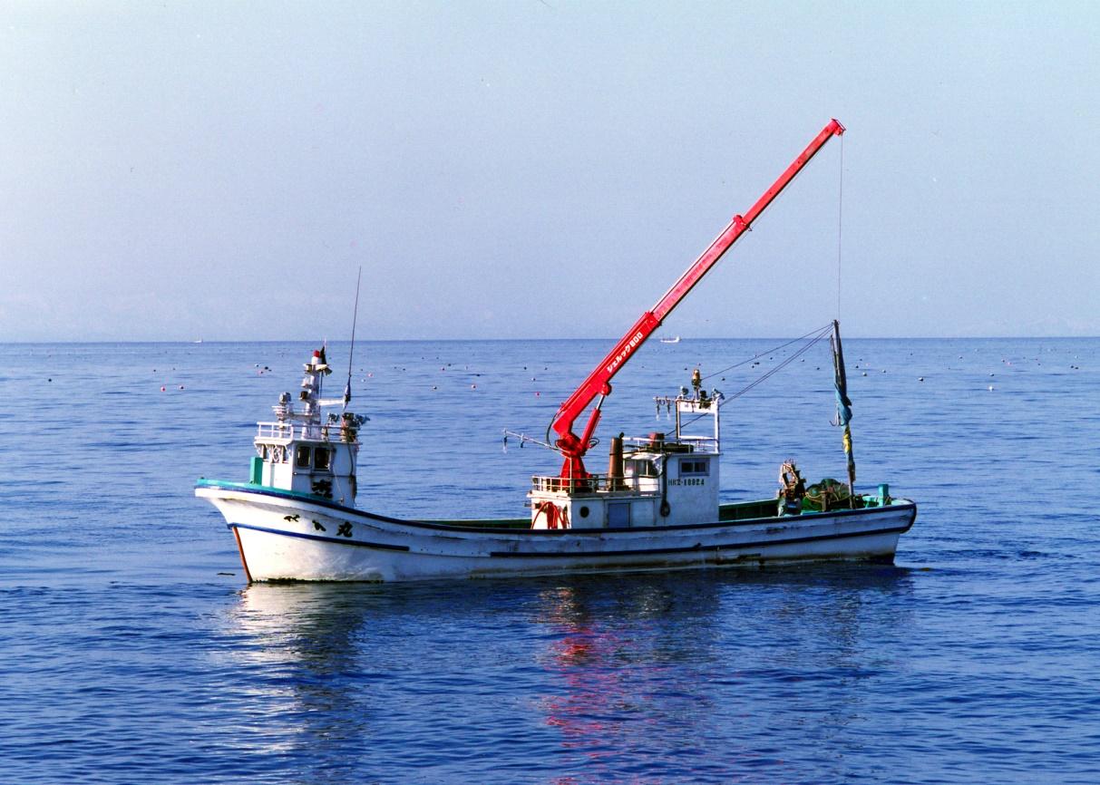
Shellook hydraulic CraneThis is the hydraulic crane which has been developed especially for vessels.
Shellook
There are three types of Shellooks (300, 500,500A)which can be used for small vessels, etc.
Shellook Hydraulic Cranes are sold on our own design and fabrication.
Shellook 300 is smaller than other products and is a bestseller model for small vessels with high durability due to the use of stainless parts and corrosion-resistant zinc plating.
This is the hydraulic crane which has been developed especially for vessels.
The structure is very rigid in response to the load caused by the influence of waves.
For more corrosion-resistance, molten zinc plating is used for a main body and the stainless rod or double hard chrome plating processing is being done.
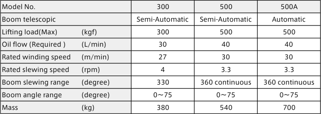
This model has three types; 300kg and 500kg hoisting ability, Automation and Semi-Automation of a boom. And it is widely adopted for small vessels
as well as ones for cultured scallops and oysters.
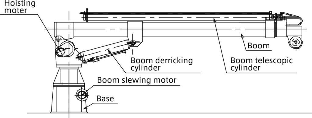
Construction of Shellook
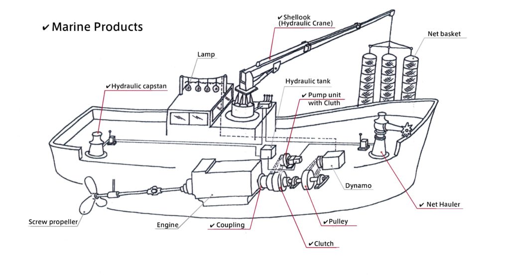
SUGA’s Marine Products (✔️)
Shellook Specification
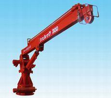 Shellook 300 |
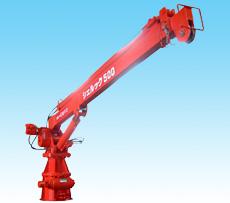 Shellook 500 |
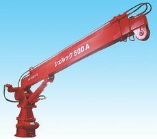 Shellook 500A |
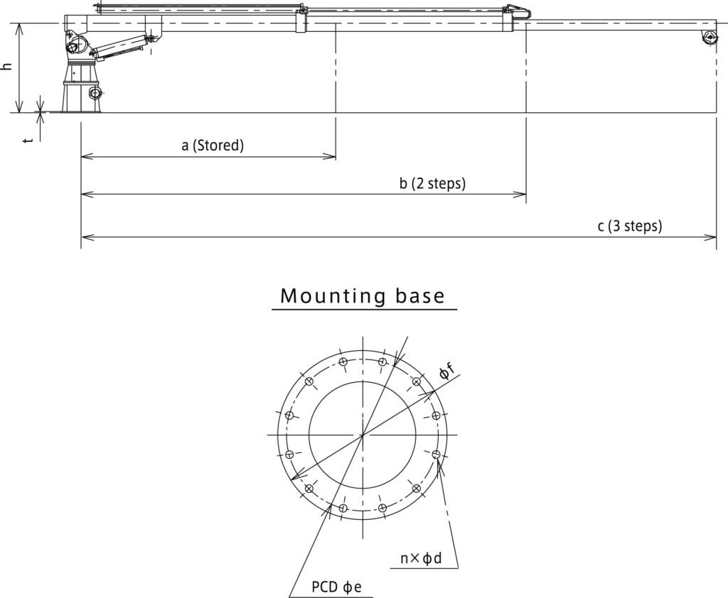
Shellook Outer dimension

I Main calculation formula of hydraulic pressure device
-
Hydraulic pump
- 1) axis input of a pump
Ls=(P・Q/60η)・102 - 2) Oil power of the pump
Lp= P・Q/60=η・Ls・10-2 - 3) Total efficiency of the pump
η=ηv・ηt・10-2 - 4) Capacity efficiency of the pump
ηv=(Q/Qth)・100≒(Q/Q0)・100 - 5) Efficiency of the motor
ηe= Ls/ Le
- 1) axis input of a pump
-
Hydraulic motor
- 1) Theoretical Displacement volume of Hydraulic motor
Dth=(2π・T)/(P・ηt)・102 - 2) Output power of Hydraulic motor
Ls=2π・T・N/60000=η・(P・Q/60)・102 - 3) Input power of Hydraulic motor
Lm=P・Q/60 - 4) Capacity efficiency of Hydraulic motor
ηv= (Dth・N/Q)・10-1 - 5) Torque efficiency of Hydraulic motor
ηt= (2π・T/P・Dth )・102 - 6) Total efficiency of Hydraulic motor
η=ηv・ηt・102= (Ls/ Lm)・102=(2π・T・N/P・Q)・10-1
- 1) Theoretical Displacement volume of Hydraulic motor
-
Cylinder
- 1) Necessary pressure to a cylinder
P1=(1/ A1)・(F/ηc+P2・A2・102) ・10-2 - 2) Necessary flow rate for a cylinder
Q= A1・v・10-1+QL - 3) Driving force of a cylinder
Acceleration ability
F1=m・α=m・v1/t
Static wear resistance
F2= μs・m・g
Dynamic wear resistance
F3= μd・m・g
- 1) Necessary pressure to a cylinder
The explanations of symbols
Ls: input of pump shaft, output power of the motor, the output power of the motor (kW)
Lp: oil power of the pump (kW)
Le: input power of the motor (kW)
Lm: input power of the motor (kW)
P: Discharge pressure of pump, differential-pressure of the input/output port of a motor (MPa)
P1: necessary pressure to cylinder (MPa)
P2: pressure of the cylinder inflow (MPa)
Q: discharge amount at the time of discharge pressure P,
inflow oil amount to the motor, necessary flow rate of the cylinder (large/min)
Qth: theoretical discharge amount (l/min)
Qo: discharge amount at the time of discharge pressure P≒0, (l/min)
QL: Leak inside the cylinder (l/min)
T: shaft torque (N・m)
N: number of rotations (min-1)
η: Total efficiency of the pump, total efficiency of the motor (the %)
η v: capacity efficiency of pump, capacity efficiency of the motor (the %)
η t: torque efficiency of pump, torque efficiency of the motor (the %)
η e: efficiency of motor (the %)
η c: driving force efficiency of cylinder (0.9-0.95)
Dth: theoretical displacement volume of the motor (cm3/rev)
A1: inlet side pressure receiving area of cylinder (cm2)
A2: outlet side pressure receiving area of cylinder(cm2)
F: cylinder driving force (N)
F1: cylinder acceleration force (N)
F2: static wear resistance (N)
F3: dynamic wear resistance (N)
v: The speed of the cylinder (m/min)
v1: The speed after acceleration (m/s)
m: The mass of the load (KG)
α: acceleration (m/s2)
t: acceleration time (s)
μ s: static friction coefficient
μ d: dynamic friction coefficient
g: acceleration of the gravity (m/s2)

