Cubic Sputtering EquipmentSputtering equipment is a PVD-type thin film forming equipment that utilizes the sputtering phenomenon in which ionized Ar gas under plasma discharge collides with a target at high speed, and target atoms ejected by the collision are deposited on the substrate.
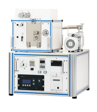
SSP1000
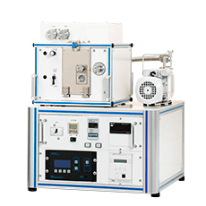
Affordable Desk-Top type RF sputtering equipment
Deposition direction can be changed even after the installation
POINT
- Film thickness distribution(Φ100mm): less than ±5%
- Deposition direction is selectable from 3 choices
- Easy set up by users
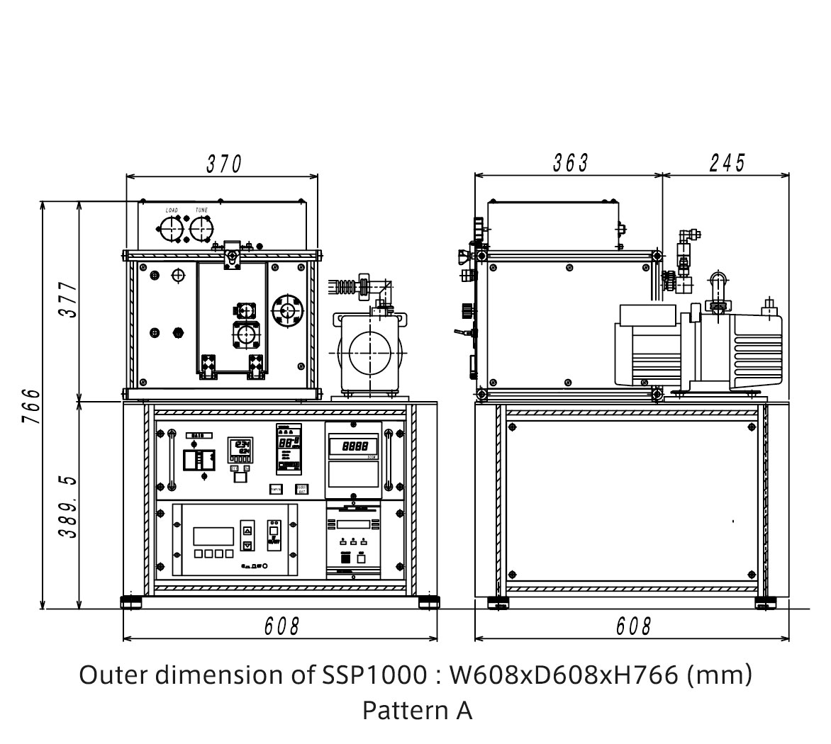
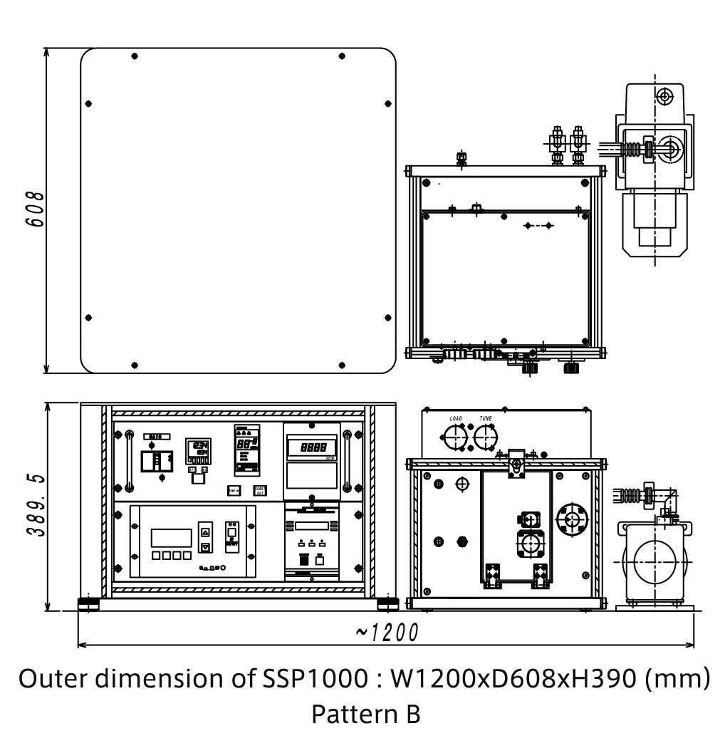
Outer dimensions (Main unit)
W608mm × D608mm × H766mm
| Cathode | Uniformity | Substrate heater | Combination |
|---|---|---|---|
| 1 piece | ≦±5%(Substrate rotation) | Not Applicable | × |
Outline・Application
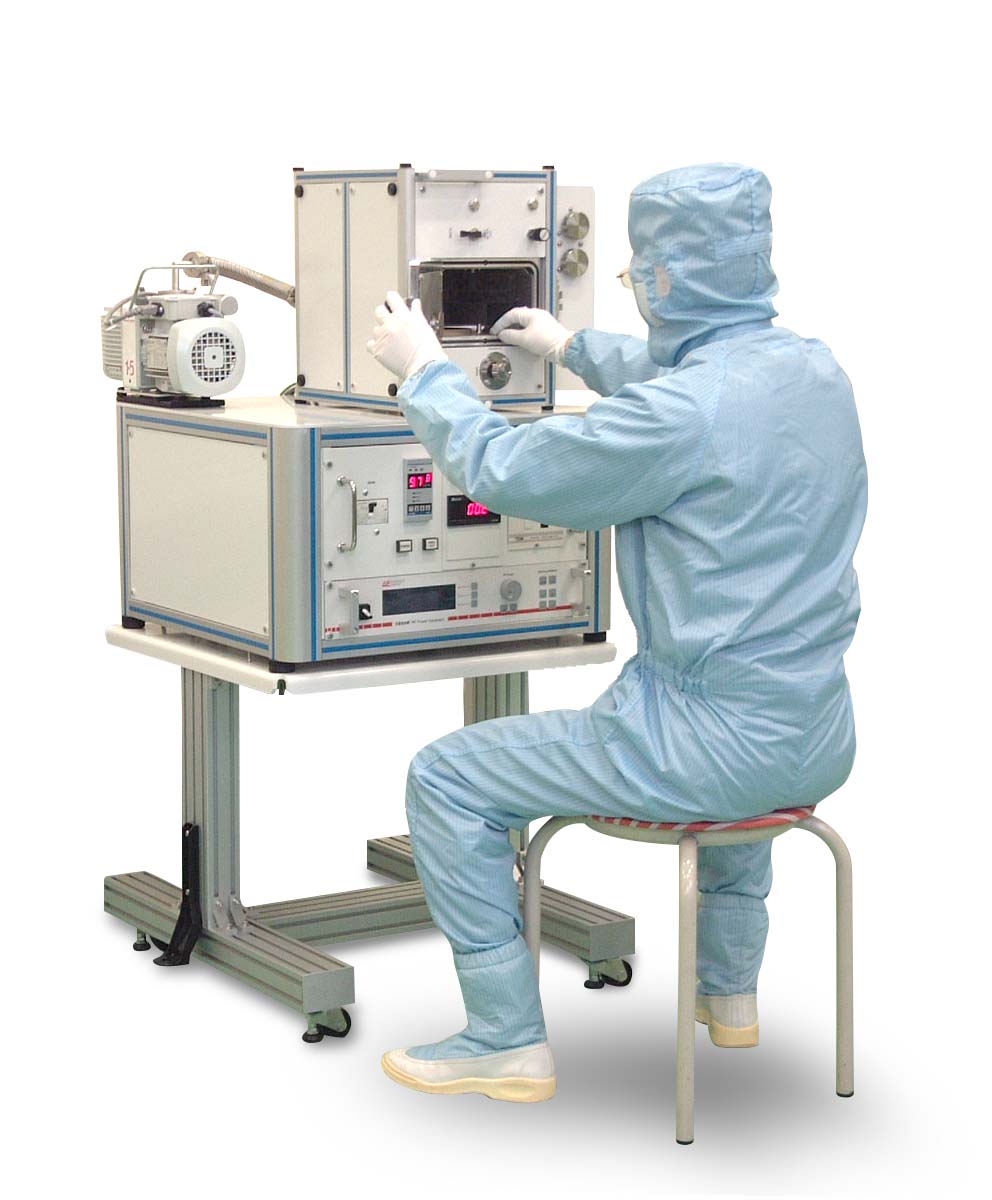
Desk-Top type RF sputtering equipment for R&D
It plays an active role in R&D applications such as metal films, insulating films, conductive films, protective films, reflective films, catalysts, coatings, circuits, batteries, MEMS and new advanced material.
The chamber is 31kg lightweight by cutting out from the aluminum block.
Depending on how the chamber is placed, the deposition direction can be selected from UP, SIDE and DOWN.
Features
【Feature1】The same cathode as that of the high end model
It has one φ2 inch magnetron cathode (with shutter) and is applicable for film thickness distribution within φ 100mm, less than ± 5%. Even though this is the low end model, the same cathode structure as the higher model is adopted.
For film deposition on the magnetic material, take out the water-cooled magnet and replace it with a strong magnetic field magnet (optional item).
【Feature2】Selectable sputtering direction
As the name of ‘Cubic Sputter’ shows, the shape of the chamber (deposition room) is like a dice and deposition direction can be changed by how it’s placed: Sputter UP, Spatter SIDE, and Sputter DOWN.
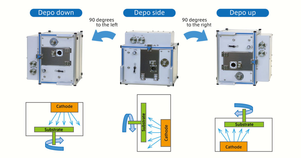
・Depo up(↑)
This deposition direction prevents the adhesion of particles to the substrate. Excellent workability during maintenance because the target faces downward
・Depo side(←)
This arrangement prevents particles on the substrate and flakes from adhering to the target and enables high-quality film formation.
It’s superior for fine-adjustment of the distance between the target and the substrate (T / S).
・Depo down(↓)
In this direction, a sample is simply placed on a substrate holder, so it’s applicable for the irregular dimension substrate or small parts to be placed side by side. It may need a special attention because particles easily fall onto the substrate.
It is necessary to pull out the gas and cooling water when changing the placement of the chamber so these utilities shall be connected with a flexible hose and tubes instead of rigid pipes.
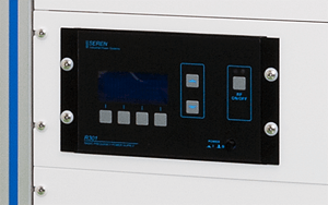
【Feature3】RF power supply (With pulse mode)
Stable film formation can be obtained even for insulating material targets which can cause abnormal discharge due to the high-frequency RF power supply with a pulse oscillation function.Stable film formation can be obtained even for insulating material targets which can cause abnormal discharge due to the high-frequency RF power supply with a pulse oscillation function.
【Feature4】Automated vacuum exhaust system
To start and stop operations for vacuum, SSP1000 is operable with just one button. The rotary pump is started and ten, the turbo molecular pump is started up to the steady rotation in order. The rotary pump is stopped after the turbo molecular pump is stopped, and all subsequent operations up to the atmospheric vent are performed automatically. In addition, it is possible to see whether it’s in vacuum process or stop mode according to the light of the button. It’s designed to prevent the risk of accidental damages during the operation of vacuum.
【Feature5】Operation systems by manual
Various functions and operation systems are efficiently arranged for the film formation such as RF power supply control, pressure display, flow rate display, sputter timer, volume for matching, substrate rotation button, gas introduction and flow rate adjustment, shutter, buzzer function, etc.
* A heater ON / OFF switch shall be added for the chamber bake function (option).
【Feature6】Interlock function
Vacuum system and RF power supply have the interlock to prevent the damage due to the incorrect operation or runaway. In particular, the RF power supply shall be applied for the plasma discharge only if it can satisfy a number of conditions such as vacuum pump operation signal, vacuum gauge pressure information, cooling water sensor signal, etc
【Feature7】2 types of placements possible
Stack arrangement (layered) and parallel arrangement (horizontal) is available to accommodate various situation of the installation site. It is also possible to place the power supply unit and pump on the floor and place the chamber unit separately on the rack. Length of the cables needs to be arranged accordingly.
In addition, a special stand (for stack placement) is also available as an option.
 |
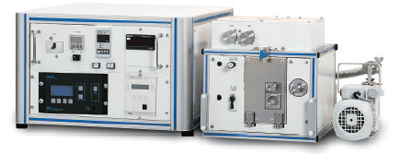 |
| Pattern A | Pattern B |
【Feature8】System installation can be done by users
As the standard, installation and operation training shall be provided by our service personnel at the time of delivery. However, it is not difficult to set up by the user if you are familiar with vacuum equipment (especially sputtering equipment). Easy wiring is possible by labels and different shape connectors to be identified. With regard to cooling water, process gas, and electricity, it is rather simple if you have experience connecting utilities. In case there is any doubt for the operations and/or daily maintenance after carefully reading the manuals, please get proper training to prevent accidents.
Promotion Video
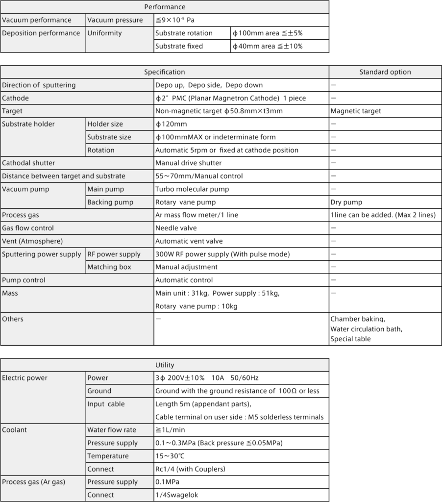
SSP1000 Specification
SSP1000 Outer dimension
OPTION
Various options are available.
1.Deposition of magnetic materials
In case of film deposition with magnetic materials such as iron (Fe), a stable plasma discharge cannot be obtained by the standard magnetron cathode.
Therefore, it is possible to select the specifications of the cathode for magnetic materials. Even after the installation, both magnetic and non-magnetic materials can be used by parts replacement.
2.Deposition of thin targets
The dimension of cathode is φ50.8mm x t3mm as the standard. For the demand to minimize the cost for the target to be 3mm thick or for the less frequent film deposition, shield and target holder for thin targets such as 1 mm and 2 mm is available.
* Depending on the material, thin targets may be difficult to be discharged.
* Abnormal discharge may occur in the extra space between the target and the shield when thin target is sputtered in combination with standard 3mm thick parts and film deposition may not be established.
3.Additional process gas introduction
Additional process gas introduction system can be added to be 2 lines. It is necessary for reactive sputtering to introduce oxygen or nitrogen.
4.Chamber baking function
Aluminum chambers can be baked with cassette heaters to improve ultimate vacuum.
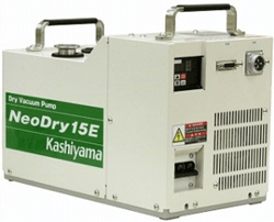
5.Replaced to dry pump
The subsidiary pump can be replaced from rotary pump to dry pump. Basically, a dry pump is required in a clean room. Our non-contact multi-stage roots type dry pump can offer maintenance-free clean vacuum condition over a long period of time.
6.Special stand
Specialized stand for SSP1000 is available. The table and power supply can be fixed with screws. Due to the characteristics of the equipment, it has a high center of gravity and the platform uses a thick frame to ensure stability. A bracket for anchoring to the floor is also included for earthquake countermeasures.
TECHNOLOGY
SUGA’s Sputtering Equipment
Sputtering equipment is a film-forming equipment that uses sputtering method, which is classified as physical vapor deposition (PVD) within the category of vacuum thin film formation. Thin films obtained by sputtering equipment have excellent adhesion to substrates, high reproducibility during repeated film formation, and the ability to produce high melting point materials and alloys. It is also possible to produce oxide and nitride films as well as metal films and insulating films that are indispensable for functional materials such as semiconductors and electronic devices.
SUGA Co., Ltd. has applied technology and strict quality standards that has been accumulated over many years as a partner company of a major vacuum equipment manufacturer to its own brand equipment which makes it possible to design and manufacture user-friendly, robust, high quality sputtering equipment to meet the customer’s needs.
Feature of sputtering
• Since the impact energy of the material that collides with the substrate is strong, a thin film with high adhesion can be obtained.
• Since the material flies linearly in a certain direction, the film adheres less to other than the substrate compared to the conventional deposition methods. However, a film is difficult to adhere to the side wall surface of the uneven portion.
• Film thickness can be easily controlled by adjusting various conditions such as power supply and deposition time.
• A film with a uniform thickness can be formed over a wide area.
• High melting point materials and insulating films can be formed.
• When making an alloy, the composition of the material is less likely to be changed compared to a vapor deposition that melts the material at a high temperature.
• Compound film also can be obtained by reactive sputtering combining nitrogen, oxygen, hydrogen, etc.
• Deposition surface of the substrate can be plasma cleaned (reverse sputtering) by applying high pressure to the substrate holder.
• The deposition speed (deposition rate) is slower than the vapor deposition.
The structure and principle of the sputtering equipment
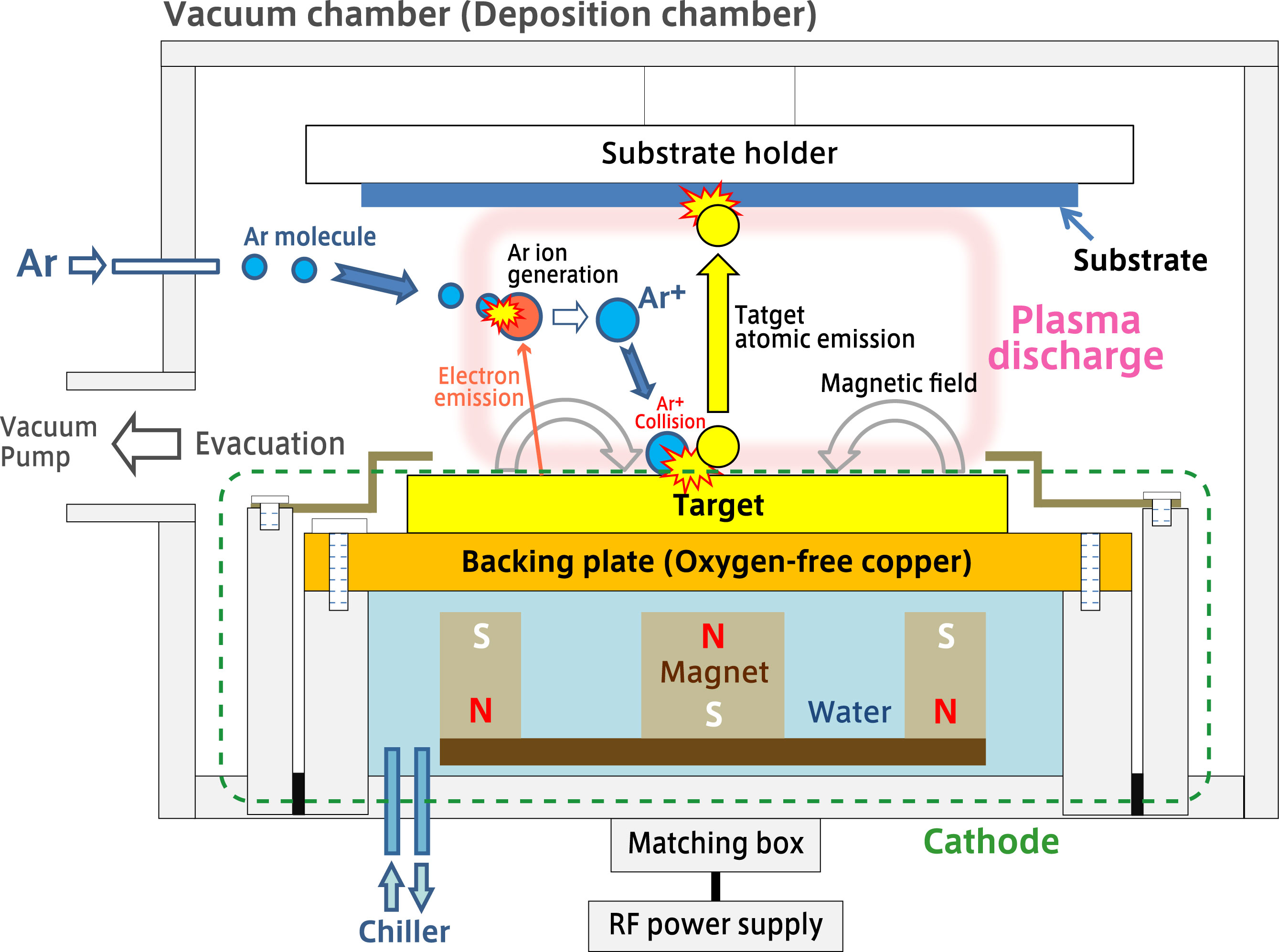
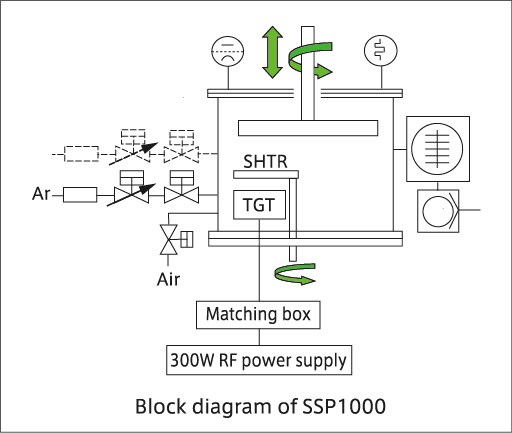
01.Vacuum chamber
The cathode (electrode) for mounting the target material and the substrate (wafer) are placed to be opposite in the vacuum chamber. The distance between them is about several tens to hundred mm.
The figure shows an example of sputter up (face down) in which the deposition direction is from bottom to top. The sputter-up arrangement has two advantages: it prevents foreign material to adhere to the substrate surface, and the cathode side with a water cooling mechanism is easy to maintain.
Sputter down (face up) arrangement with the mechanism turned upside down is useful for film deposition that cannot be fixed.
A sliding shutter plate is placed between the cathode and the substrate so that the film formation timing can be controlled.
02.Cathode
SUGA Co., Ltd. employs PMC (Planar Magnetron Cathode) system. The green dotted line in the figure explains collectively called the cathode.
An oxygen-free copper back plate (backing plate) is placed on the back of the sputtering target, which is the film forming material. Although many metal-based targets can be deposited properly when it’s placed on a backing plate, compound targets are often required “bonding process” to bond to the backing plate in order to increase cooling efficiency and prevent cracking and breakage of the material.
Whole series of services are available from target arrangement to bonding processing.
A water-cooled permanent magnet is placed under the back plate. A ring-shaped magnet and a cylindrical magnet are fixed to the base of the disk (Yoke) although the figure appeared to be showed that three magnets are arranged. A circular tunnel is formed on the target where the magnetic field generated by the magnet and the electric field generated by the application of voltage are orthogonal to each other, and a high-density plasma discharge is generated in this area.
03.Vacuum, and Ar gas
To generate plasma discharge, first evacuate the vacuum vessel (film formation chamber). In general, 0.2~10Pa is good enough for plasma discharge but for the purpose of producing high-quality thin films, it is desirable to reduce the gas components (outgas) released from the inner walls and structures of the equipment under vacuum as well as residual gas typified by water present in the deposition chamber as much as possible
Therefore, a turbo molecular pump is employed that can reduce pressure to the high vacuum range. Depending on the specifications of the equipment and pump, a certain amount of time will be required to obtain 10-5 Pa or even lower.
After reducing the pressure to the ultimate vacuum, keep the pressure at about 0.5Pa after plasma excitation while introducing a high-purity argon gas.
The reason why argon gas is used in the sputtering equipment is that the sputtering rate is relatively good and the inert gas should make it difficult for chemical reactions with other materials to occur. Argon is also popular because of its high purity and low costs.
N2 and O2 may be used for reactive sputtering other than argon. Rare gases such as He, Ne, Kr, and Xe may be used for other purposes.
04.Plasma discharge
By RF sputtering power supply, voltage is applied to the cathode and electrons emitted from the target surface collide with floating argon molecules. Electrons are knocked out of the argon molecules by collision and Ar + ions are generated. Electrons have the property of flowing into the conductive body, but there is no escape near the target under the plasma. As a result, the density of plasma increases near the magnetic field above the target, and Ar + ions are generated efficiently.
Ar + ions, which are accelerated by an electric field under plasma, fly and collide at high speed (thousands of kilometers per second) toward the cathode surface. The phenomenon that Ar + ions blow off target atoms is called sputtering.
The atoms on the cathode surface are sputtered by collision with Ar ions, and collide at high speed (10,000 km per hour) at the opposite substrate side. A thin film is gradually formed on the surface of the substrate due to repeated collisions of atoms of the target material. Since atoms collide with strong kinetic energy on the substrate surface, the thin film formed by sputtering equipment has excellent adhesion.
05.RF power supply
As the standard, SUGA Co., Ltd. employs RF power supply for its Sputtering equipment. RF sputter is equipped with a 13.56MHz high frequency AC power supply (RF power supply) and matched in the matching box, and discharged while switching the anode and cathode at high speed.
For insulating target material, discharge does not last in DC power sourced sputtering equipment whereas RF power sourced sputtering equipment can stably maintain plasma and has better flexibility. In addition, since an RF power supply with a pulse function is adopted as standard, insulation targets that are prone to abnormal discharge can be also handled.
Please get the local consultation for the installation of high frequency wave equipment.
Send us an inquiry if you have any questions.