Sputtering Equipment (Expandable type)Sputtering equipment is a PVD-type thin film forming equipment that utilizes the sputtering phenomenon in which ionized Ar gas under plasma discharge collides with a target at high speed, and target atoms ejected by the collision are deposited on the substrate.
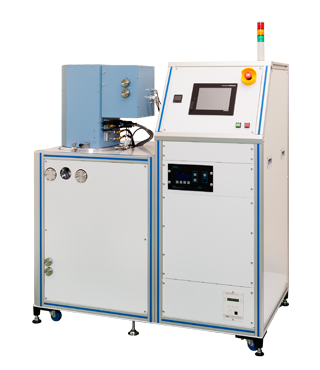
SSP3000Plus
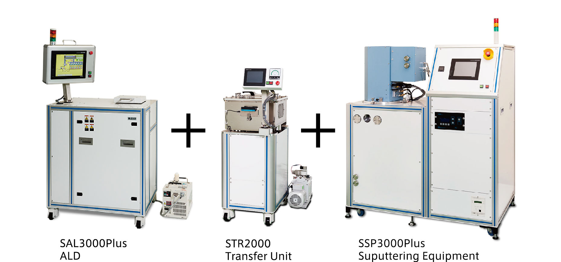
This model can be easily combined with ALD and Annealing equipment at a later stage.
POINT
- High performance model of triple cathode
- Film thickness distribution within φ100mm ± 3% or less
- Another Plus series can be connected with this model
Outer dimensions (Main unit)
W1308mm × D840mm × H1728mm
| Cathode | Uniformity | Substrate heater | Combination |
|---|---|---|---|
| 3 pieces | ≦±3%(Substrate rotation) | 300℃ (800℃) | ✔ |
Outline・Application
High performance, multi-function sputtering equipment
Active in a wide range of fields from R&D to small-scale production of metal films, insulating films, conductive films, insulating films, protective films, reflective films, alloys, catalysts, coatings, circuits, batteries, MEMS, and new material development.
By connecting with Plus series equipment, it is possible to perform advanced thin film manufacturing processes, such as lamination in combination with ALD equipment, heat treatment with annealing equipment, gas replacement treatment, etc.
Feature
【Feature1】High quality film formation
Equipped with three φ2 inch magnetron cathodes (with shutters), achieving a film thickness distribution of ± 3% or less within φ100mm. It’s considered as the top class quality in Japan(according to our survey).
This equipment can also be used for single-layer, multi-layer, and alloy film formation.

【Feature2】High temperature substrate heating
With regard to the substrate heating function that affects the film quality, MAX800 ° C (monitor temperature) can be achieved by radiant heater as the option whereas the standard specification is up to MAX300 ° C.
The surface temperature of the actual substrate shall be confirmed at the pre-shipment inspection.
【Feature3】RF power supply (With pulse mode)
Stable film formation can be obtained even for insulating material targets which can cause abnormal discharge due to the high-frequency RF power supply with a pulse oscillation function.
【Feature4】Expandability
A load lock chamber can be provided by connecting with STR2000 using an expansion port placed at the side of the main unit.
Also, this model can be combined with other Plus series such as Sputtering, ALD, Annealing and vapor deposition equipment to deposit substrates without exposure to the atmosphere.
【Feature5】User Friendly Design
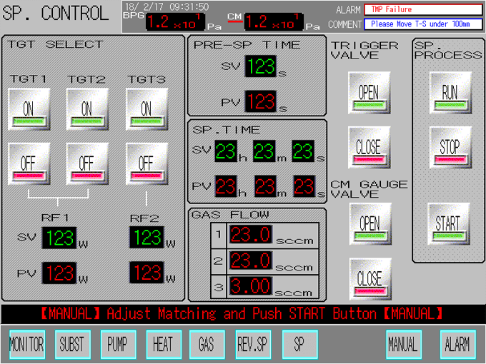
The touch screen is placed at the elevation angle, and it is designed in consideration of better visibility and operability.
The program employs a GUI (Graphical User Interface) that allows the operator to understand intuitively and it has good visibility with respect to various statuses, including operating conditions and good operability to make easy adjustment for valves and setting items.
In addition, this touch screen program guarantees safety and operability with various interlocks and alarm functions.
Responding to the daily changing research or the equipment modifications,
the program was designed so that the modification can be easily done.
For this design it can result in the reduction of the program design cost.
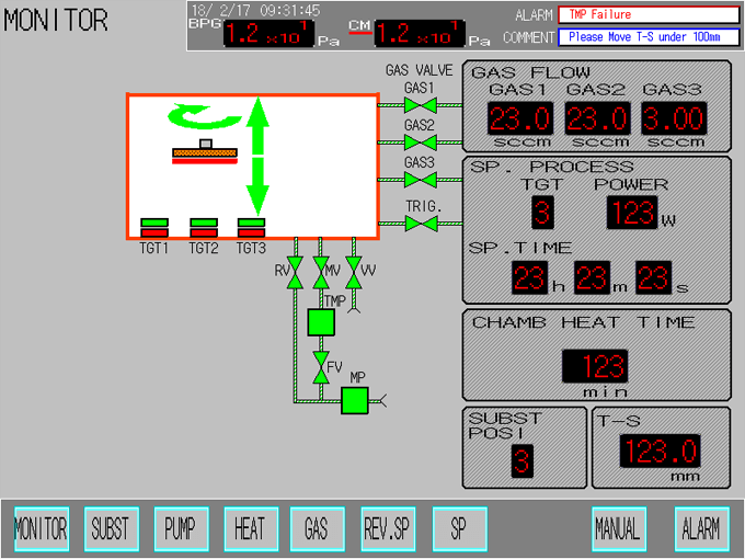
Monitor (Main display)
<!–
スパッタコントロール画面(成膜条件設定)

マニュアルポンピング画面(排気系手動操作用)
–>
【Feature6】Integrated design
A main unit and control box was designed as an integration type. Due to this simple design, this model can be easily moved and requires less work at the time of the layout change at a later stage.
【Feature7】Various options
Various options are available for SSP3000Plus.Modification to add those options shall be arranged upon request before/after the installation. Some of those modifications may not be conducted after installation. Please contact us for details.
The connection with ALD and Annealing equipment can be easily done via STR2000 at a later stage.
SSP3000Plus Specification
SSP3000Plus Outer dimension
![]()
OPTION
Various options are available.
1.Deposition of magnetic materials
In case of film deposition with magnetic materials such as iron (Fe), a stable plasma discharge cannot be obtained by the standard magnetron cathode.
Therefore, it is possible to select the specifications of the cathode for magnetic materials. Even after the installation, both magnetic and non-magnetic materials can be used by parts replacement.
2.High Temperatureheating substrate
With regard to the substrate heating function that affects the film quality, MAX800 ° C (monitor temperature) can be achieved by radiant heater as the option where as the standard specification MAX300 ° C.
The surface temperature on the actual substrate shall be confirmed at the pre-shipment inspection.
3.Deposition of thin targets
The dimension of cathode is φ50.8mm x t3mm as the standard. For the demand to minimize the cost for the target to be 3mm thick or for the less frequent film deposition, shield and target holder for thin targets such as 1 mm and 2 mm is available.
* Depending on the material, thin targets may be difficult to be discharged.
* Abnormal discharge may occur in the extra space between the target and the shield when thin target is sputtered in combination with standard 3mm thick parts and film deposition may not be established.
4.Sputtering Power Source
One RF power supply and one DC power supply can be added respectively. Three-way simultaneous discharge sputtering with two RF power source and one DC power source is possible.
Simultaneous discharge is used to increase the deposition rate and to produce alloys.
5.Automated Matching Device
By changing the manual matching box of the RF power supply to an auto-matching box, discharge under optimal conditions can be maintained.
In addition, it’s capable for fully automated film formation with recipes.
6.Reverse sputtering mechanism
By adding a reverse sputtering mechanism, it is possible to clean the surface by removing the oxide film adhered to the substrate surface as a pretreatment for film formation.
Matching box (for Reverse sputtering)
7.High speed rotation of substrate
It is possible to increase the substrate rotation speed from the standard 5rpm to 50rpm.
Improved uniformity of the film thickness and good effect on alloy film formation by multi-source simultaneous sputtering is expected.
8.Additional process gas introduction
Max. 2 process gas introduction systems can be equipped with.
The reactive sputtering to introduce oxygen or nitrogen requires this addition.
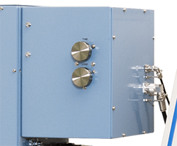
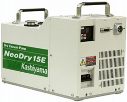
9.Replaced to dry pump
The subsidiary pump can be replaced from rotary pump to dry pump. Basically, a dry pump is required in a clean room. Our non-contact multi-stage roots type dry pump can offer maintenance-free clean vacuum condition over a long period of time.
TECHNOLOGY
SUGA’s Sputtering Equipment
Sputtering equipment is a film-forming equipment that uses sputtering method, which is classified as physical vapor deposition (PVD) within the category of vacuum thin film formation. Thin films obtained by sputtering equipment have excellent adhesion to substrates, high reproducibility during repeated film formation, and the ability to produce high melting point materials and alloys. It is also possible to produce oxide and nitride films as well as metal films and insulating films that are indispensable for functional materials such as semiconductors and electronic devices.
SUGA Co., Ltd. has applied technology and strict quality standards that has been accumulated over many years as a partner company of a major vacuum equipment manufacturer to its own brand equipment which makes it possible to design and manufacture user-friendly, robust, high quality sputtering equipment to meet the customer’s needs.
Feature of sputtering
• Since the impact energy of the material that collides with the substrate is strong, a thin film with high adhesion can be obtained.
• Since the material flies linearly in a certain direction, the film adheres less to other than the substrate compared to the conventional deposition methods. However, a film is difficult to adhere to the side wall surface of the uneven portion.
• Film thickness can be easily controlled by adjusting various conditions such as power supply and deposition time.
• A film with a uniform thickness can be formed over a wide area.
• High melting point materials and insulating films can be formed.
• When making an alloy, the composition of the material is less likely to be changed compared to a vapor deposition that melts the material at a high temperature.
• Compound film also can be obtained by reactive sputtering combining nitrogen, oxygen, hydrogen, etc.
• Deposition surface of the substrate can be plasma cleaned (reverse sputtering) by applying high pressure to the substrate holder.
• The deposition speed (deposition rate) is slower than the vapor deposition.
The structure and principle of the sputtering equipment
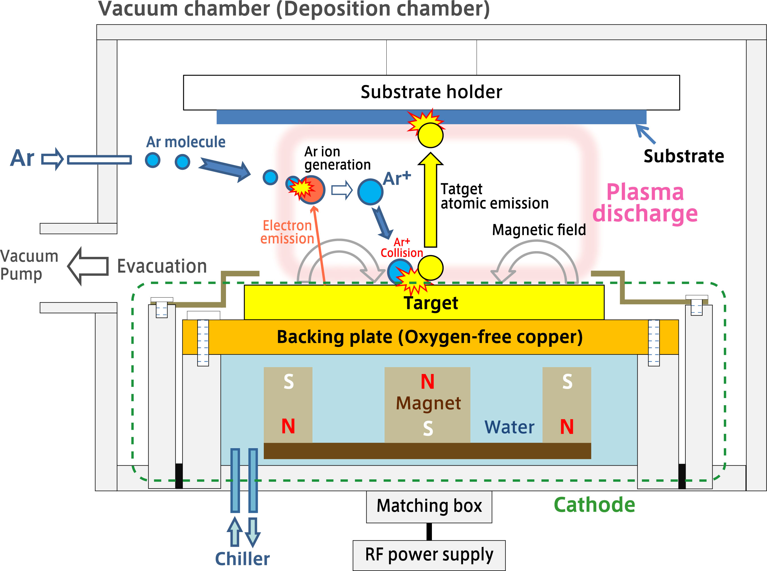
01.Vacuum chamber
The cathode (electrode) for mounting the target material and the substrate (wafer) are placed to be opposite in the vacuum chamber. The distance between them is about several tens to hundred mm.
The figure shows an example of sputter up (face down) in which the deposition direction is from bottom to top. The sputter-up arrangement has two advantages: it prevents foreign material to adhere to the substrate surface, and the cathode side with a water cooling mechanism is easy to maintain.
Sputter down (face up) arrangement with the mechanism turned upside down is useful for film deposition that cannot be fixed.
A sliding shutter plate is placed between the cathode and the substrate so that the film formation timing can be controlled.
02.Cathode
SUGA Co., Ltd. employs PMC (Planar Magnetron Cathode) system. The green dotted line in the figure explains collectively called the cathode.
An oxygen-free copper back plate (backing plate) is placed on the back of the sputtering target, which is the film forming material. Although many metal-based targets can be deposited properly when it’s placed on a backing plate, compound targets are often required “bonding process” to bond to the backing plate in order to increase cooling efficiency and prevent cracking and breakage of the material.
Whole series of services are available from target arrangement to bonding processing.
A water-cooled permanent magnet is placed under the back plate. A ring-shaped magnet and a cylindrical magnet are fixed to the base of the disk (Yoke) although the figure appeared to be showed that three magnets are arranged. A circular tunnel is formed on the target where the magnetic field generated by the magnet and the electric field generated by the application of voltage are orthogonal to each other, and a high-density plasma discharge is generated in this area.
03.Vacuum, and Ar gas
To generate plasma discharge, first evacuate the vacuum vessel (film formation chamber). In general, 0.2~10Pa is good enough for plasma discharge but for the purpose of producing high-quality thin films, it is desirable to reduce the gas components (outgas) released from the inner walls and structures of the equipment under vacuum as well as residual gas typified by water present in the deposition chamber as much as possible
Therefore, a turbo molecular pump is employed that can reduce pressure to the high vacuum range. Depending on the specifications of the equipment and pump, a certain amount of time will be required to obtain 10-5 Pa or even lower.
After reducing the pressure to the ultimate vacuum, keep the pressure at about 0.5Pa after plasma excitation while introducing a high-purity argon gas.
The reason why argon gas is used in the sputtering equipment is that the sputtering rate is relatively good and the inert gas should make it difficult for chemical reactions with other materials to occur. Argon is also popular because of its high purity and low costs.
N2 and O2 may be used for reactive sputtering other than argon. Rare gases such as He, Ne, Kr, and Xe may be used for other purposes.
04.Plasma discharge
By RF sputtering power supply, voltage is applied to the cathode and electrons emitted from the target surface collide with floating argon molecules. Electrons are knocked out of the argon molecules by collision and Ar + ions are generated. Electrons have the property of flowing into the conductive body, but there is no escape near the target under the plasma. As a result, the density of plasma increases near the magnetic field above the target, and Ar + ions are generated efficiently.
Ar + ions, which are accelerated by an electric field under plasma, fly and collide at high speed (thousands of kilometers per second) toward the cathode surface. The phenomenon that Ar + ions blow off target atoms is called sputtering.
The atoms on the cathode surface are sputtered by collision with Ar ions, and collide at high speed (10,000 km per hour) at the opposite substrate side. A thin film is gradually formed on the surface of the substrate due to repeated collisions of atoms of the target material. Since atoms collide with strong kinetic energy on the substrate surface, the thin film formed by sputtering equipment has excellent adhesion.
05.RF power supply
As the standard, SUGA Co., Ltd. employs RF power supply for its Sputtering equipment. RF sputter is equipped with a 13.56MHz high frequency AC power supply (RF power supply) and matched in the matching box, and discharged while switching the anode and cathode at high speed.
For insulating target material, discharge does not last in DC power sourced sputtering equipment whereas RF power sourced sputtering equipment can stably maintain plasma and has better flexibility. In addition, since an RF power supply with a pulse function is adopted as standard, insulation targets that are prone to abnormal discharge can be also handled.
Please get the local consultation for the installation of high frequency wave equipment.
Send us an inquiry if you have any questions.