Sputtering system is the deposition equipment using the sputtering method, which is classified as a physical vapor deposition (PVD) within the category of vacuum thin film formation.
Thin films produced by sputtering equipment feature excellent adhesion to substrates, high reproducibility when repeatedly depositing films, and the ability to produce materials and alloys with high melting points. In addition, it can produce oxide and nitride films as well as metal films and insulating films, which are indispensable for functional materials such as semiconductors and electronic devices.
We design and manufacture high quality sputtering equipment that reflects the needs of our customers by applying the technology and strict quality standards we have proliferated over many years as a subcontractor for major vacuum equipment manufacturers to our own products.
[Characteristics of sputtering method]
- The high collision energy of the material impacting the substrate results in a thin film with high adhesion strength.
- As the material sputters linearly in a fixed direction, there is less film adhesion to non-substrate surfaces compared to other deposition methods. However, it is difficult for the film to adhere to the sidewalls of uneven surfaces.
- Easy control of film thickness by adjusting various conditions such as supplying power and deposition time.
- A film of uniform thickness can be produced over a large area.
- High-melting-point materials and insulating films can also be deposited.
- Compared to evaporation systems, which melt materials at high temperatures when making alloys, changes in the composition of the material are less likely to occur.
- Reactive sputtering combining nitrogen, oxygen, hydrogen, etc. takes care of deposit compound films as well.
- Plasma cleaning (reverse sputtering) of the substrate deposition surface is also possible by applying high voltage to the substrate holder
- Lower deposition speed (deposition rate) than the evaporation method.
Contents
Product information on SUGA’s sputtering system [SSP1000].
The SSP1000 is a desk model type RF sputtering system for research and development.
It is active in a wide range of fields, research for metallic films, insulating films, conductive films, insulating films, protective films, reflective films, alloys, catalysts, coatings, circuits, batteries, MEMS and new materials development.
The chamber section is lightweight at 31 kg because body chamber section machined from the aluminum block.
Depending on how the chamber is placed, the deposition direction can be flexible like
Sputter UP, SIDE and DOWN.
[characteristic 1] It adopts the same cathode as the upper model
It carries φ 2 inches magnetron cathodal one engine (with a shutter) and achieves less than film thickness distribution ±5% within φ 100mm.
We did not compromise but adopted cathode structure same as the upper model even for this entry model.
When you want to deposit magnetic materials, you can cope with the film deposition of magnetic material by replacing a water-cooled magnet with the strong magnet field magnet (option).
[characteristic 2] The film formation direction can be selected.
As the name of cubic sputter indicates, it is possible to change the deposition direction in three ways: sputtering UP, sputtering SIDE, and sputtering DOWN by pulling round the dice-shaped chamber (deposition chamber).
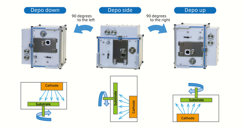
| Sputtering UP | Most of the users employ this film deposition method since this is the best way to prevent the adhesion of the particle to the substrate. It is excellent in workability during maintenance since the target faces downward. |
| Sputtering SIDE | This arrangement prevents particles from adhering to the substrate and flakes from adhering to the target and ensures high quality deposition. The workability when fine-tuning the distance between target and substrate (T/S) is superior among the three deposition directions. |
| Sputtering DOWN | It is used when arranging irregular substrates and small parts for deposition because the sample is simply placed on the substrate holder. Constant attention is required because particles tend to fall on the substrate side. When deposition direction is changed, the gas and cooling water lines need to be disconnected. It is recommended that these utilities are connected with flexible hoses and flexible tubes, etc., rather than fixed rigid piping. |
[characteristic 3] RF power supply (with pulse oscillation function)
The high-frequency RF power supply with pulse oscillation function enables stable deposition even on targets made of insulating materials, which are prone to abnormal discharges.
[characteristic 4] Automatic vacuum exhaust system
The Start and Stop operation for vacuum can be easily done with one button only.
For exhaust, the rotary pump starts up and the turbo molecular pump starts up until it rotates at a steady state. When it stops, the rotary pump stops after the turbo molecular pump stops, and then all the operations up to atmospheric venting are automatically performed.
It is also possible to recognize whether it is exhausting or stopped by the illumination of the button’s lamp.
Therefore, the equipment is designed for safe use without the risk of accidentally damaging the equipment during operations involving the exhaust system.
[characteristic 5] Operation system by the manual operation
Various gauges and operating components are efficiently arranged for the functions required during the deposition process, such as RF power control, pressure display, flow rate display, sputter timer, matching volume, substrate rotation button, gas introduction and flow rate control, shutter and buzzer functions.
If the optional chamber bake function is installed, a heater on/off switch is also added.
[characteristic 6] Interlock function
The exhaust system and RF power supply are safe to use as they are interlocked to prevent them from running out of control or being damaged by accidental operation.
In particular, the RF power supply is interlocked so that the plasma discharge is not powered unless a number of conditions are met, such as the operation signal of the exhaust system pump, the pressure information from the vacuum gauge and the cooling water sensor signal.
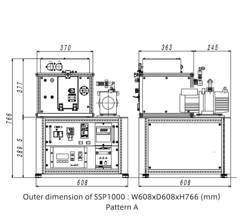
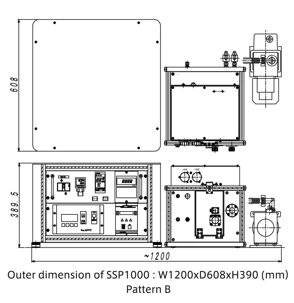
[characteristic 7] Flexible placement
Both stacked (Pattern A) and parallel (Pattern B arrangements are possible to accommodate a variety of installation environments.
Moreover, the power supply unit and pump can be floor-mounted and only the chamber can be placed on a rack.
If the power supply and chamber are to be separately installed, you are kindly requested to advise us beforehand as cable lengths etc. may be insufficient.
In addition, a dedicated stand (for stack placement) is available as an option.
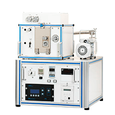
Pattern A
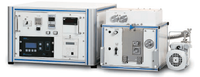
Pattern B
[characteristic 8] Installation and the setup can be done by user
Although we recommend that our service personnel provide setup and operation training when delivering SSP1000, it is not difficult for users who regularly handle vacuum equipment (especially sputtering equipment) to set it up on their own.
To facilitate wiring, different connector shapes and labels, etc. are used for identification.
The connection of cooling water, process gas, and electricity is also not difficult for those who have experience in connecting utility power.
However, if you still have concerns about the operation and daily maintenance of the unit after reading the manual, be sure to undergo operation training by us to prevent accidents.
Standard specifications for SUGA’s sputtering system [SSP1000].
SSP1000 Specification
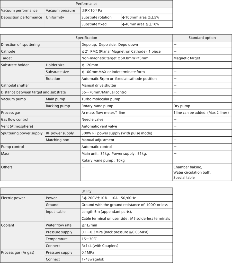
SSP1000 Outer dimensions
Options for SUGA’s sputtering system [SSP1000].
magnetic deposition
When depositing films with magnetic materials such as iron (Fe), a stable plasma discharge cannot be achieved with standard magnetron cathodes.
For magnetic materials, a cathode specification for them can be selected.
Even after the equipment has been installed, both magnetic and non-magnetic materials can be deposited by replacing those parts.
Our cathodes are ø50.8 mm x t3 mm geometry as the standard, but manufacturing a 3 mm thick target of expensive material can result in high expenditure.
If you want to reduce target expenditure or know from the outset that the number of depositions will be small, shields and target holders for thin targets such as 1 mm and 2 mm are available. Please contact us if you are concerned about the cost of the target you are using.
※Some materials are difficult to discharge on thin targets.
※Note that an abnormal discharge may occur in the extra gap created between the target and the shield and deposition may not be achieved, if a thin target is sputtered in combination with the standard parts for 3 mm thickness.
additional gas introduction systems
The maximum of two gas introduction systems are available with one additional system.
This option is required when performing reactive sputtering by introducing oxygen, nitrogen, etc.
chamber baking system
Baking of aluminum chambers with cassette-type heaters is possible.
Use this option for the purpose of improving the vacuum condition.
Up-grade to a dry pump

The auxiliary pump can be replaced from a rotary pump to a dry pump.
Basically dry pumps are required under the condition of cleanroom installation
Our selection of non-contacting, multi-stage Roots dry pumps ensures maintenance-free, clean exhaust air for a long time after installation.
Specialized frame
A dedicated trestle table is available for SSP1000.
The table can also be fixed to the power supply unit with screws.
As the center position of gravity is high due to the characteristics of the equipment, a thick frame is employed for the trestle to ensure stability.
Fittings for anchoring to the floor for earthquake protection are also included.
Repair and modification of SUGA’s sputtering system [SSP1000].
Even after the equipment is installed, we are fully prepared to meet any request.
Within the stipulated warranty period after delivery of the equipment, we will repair free of charge any initial defects or other faults that are not covered by certain conditions stipulated by us (failure due to natural disasters or improper use, etc.).
For more information, please contact us.
[Example of repair and maintenance menu]
- Routine maintenance and service response in case of malfunction
- Remodeling or adding functions to equipment and modification of the program software associated with such work
- Relocation of equipment and layout changes
- Operational training (e.g. when the person in charge of operations is replaced)
- Purchase of consumables
- Cleaning and re-blasting of the film on shielded components
- Questions to be answered by email, telephone, etc.
[Modification]
Even after the equipment has been installed, we can also provide services related to modifications due to changes in the content of experiments or conditions of use.
Examples of modification
- Combined with another device via a transfer unit (Plus series)
- Various functional additions/changes and parts replacement
- Production of sample holders for special shapes
- Program improvements and updates
- Additional gas introduction systems
- Replacement of rotary pumps with dry pumps
- Larger auxiliary pumps
- Additional cooling water circulator (chiller)
- Other remodeling and On-site services on request